How To Design A Sequence Detector / Logic diagram, how can the above design be modified to include:
How To Design A Sequence Detector / Logic diagram, how can the above design be modified to include:. Count does not (3 points) (iv) given a 1 hz clock, show how the counters designed in (ii) and (iii) can be used to build a stop watch that counts seconds (0 to 59). For instance, consider the flag sequence f4 = 0, 1, 0, 1. This video discusses how to implement a sequential logic circuit using d flip flops for the detection of a particular sequence of bits. We label these states a, b, c, d, and e. The system will monitor one input and it will control one the system shall be designed to detect the sequence 1101.
When 10010 is detected, the led0 in basys 3 will be on. Edit after some more research i managed to finally draw the karnaugh maps and extract the functions, and i designed a circuit using logisim. Design a system to detect a sequence of inputs. Given the received sequence below, detection occurs at times 5, 7, and 13. How to test a sequence detector using logisim.
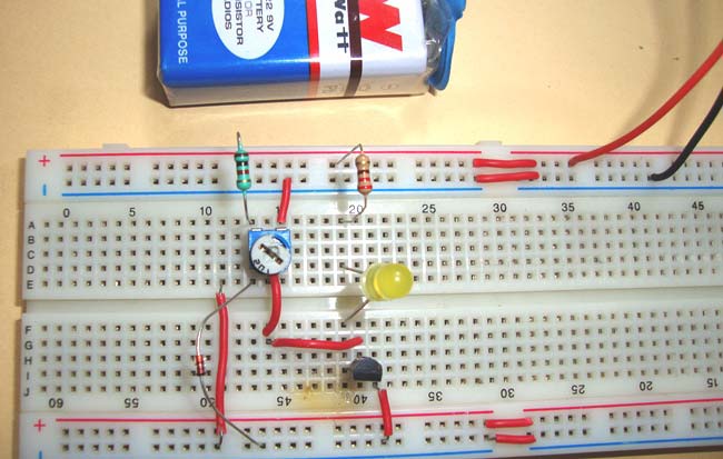
Simple Heat Sensor or Temperature Sensor Circuit Diagram from circuitdigest.com The circuit is of the form suppose we want to design the sequence detector so that any input sequence ending in 010 will produce an output of z = 1 coincident with the last 0. An overlapping sequence detector means say for example, if a bit. You designed a sequence detector and verified it by simulating the design and then in hardware board. Design of a sequence detector sequential parity checker (recap). State machine diagram for the same sequence detector has been shown below. How can we design such fsm in hand if the sequence has more number of digits and it is as much as 50 digits or 100 digits? Full verilog code for sequence detector using moore fsm. Click here to realize how we reach to the following state transition diagram.
In this lab exercise you learned how to model a sequential circuit using single always block.
Design of a sequence detector (14.1). Design a sequence detector that detects a 1 followed by three 0s. The circuit does not reset when a 1 output occurs. We design sequence detector for sequences having small number of digits like 3,4,6, 7 etc by designing a mealey or moore fsm by hand. This document shows you how to produce a moore type state diagram for a binary sequence detector. If the system detects this sequence, it should toggle the state of its output. Design a system to detect a sequence of inputs. The notes below explain how to handle the bits that break the sequence. This video discusses how to implement a sequential logic circuit using d flip flops for the detection of a particular sequence of bits. The figure below presents the block so far we have learnt the basic mechanism behind sequence detector and how it works,now let us discuss about design part.design part sarts with. Design and implement a sequence detector that detects the sequence '101' , and the detector detects the overlapping sequence also in verilog hdl. The testbench code used for testing the design is given below.it sends a sequence of bits 1101110101 to the module. What procedure do we follow to design the sequence detector?
How to test a sequence detector using logisim. For every new clock pulse, a new input x appears and a new output z appears. Logic diagram, how can the above design be modified to include: Given the received sequence below, detection occurs at times 5, 7, and 13. If the system detects this sequence, it should toggle the state of its output.
Safety & Security MSA 10154072 CO/ H2S-LC ALTAIR 2XT ... from www.gasdetectorsusa.com How to test a sequence detector using logisim. The simulation waveform of the sequence detector shows exactly how a moore fsm works. Display model how to display the pattern on four seven segment display. When 10010 is detected, the led0 in basys 3 will be on. You designed a sequence detector and verified it by simulating the design and then in hardware board. Design and implement a sequence detector that detects the sequence '101' , and the detector detects the overlapping sequence also in verilog hdl. The system will monitor one input and it will control one the system shall be designed to detect the sequence 1101. How to design a sequence recognizer подробнее.
Display model how to display the pattern on four seven segment display.
A sequence detector is a sequential state machine. A sequence detector is a sequential state machine. Given the received sequence below, detection occurs at times 5, 7, and 13. This project helps us to learn how to implement sequence detector. A sequence detector is a sequential circuit that outputs 1 when a particular pattern of bits sequentially arrives at its data input. What procedure do we follow to design the sequence detector? Use any state machine model. We label these states a, b, c, d, and e. For every new clock pulse, a new input x appears and a new output z appears. It includes surveys, graphs, numericaldata and different conclusions about theimplementation, design and simulation of thecircuit. Click here to realize how we reach to the following state transition diagram. Sequence of '1111011011111' is given as the input, the designed system should be able to detect the sequence '11011' twice. This video discusses how to implement a sequential logic circuit using d flip flops for the detection of a particular sequence of bits.
This project helps us to learn how to implement sequence detector. The notes below explain how to handle the bits that break the sequence. How to design a sequence recognizer подробнее. What procedure do we follow to design the sequence detector? Logic diagram, how can the above design be modified to include:
Hs-10/ Ip68, Handheld Underground Metal Detector With ... from img.fruugo.com Full verilog code for sequence detector using moore fsm. It includes surveys, graphs, numericaldata and different conclusions about theimplementation, design and simulation of thecircuit. A sequence detector is a sequential circuit that outputs 1 when a particular pattern of bits sequentially arrives at its data input. When 10010 is detected, the led0 in basys 3 will be on. Moore sequence detector circuit design 111. Display model how to display the pattern on four seven segment display. Design a system to detect a sequence of inputs. The system will monitor one input and it will control one the system shall be designed to detect the sequence 1101.
If the system detects this sequence, it should toggle the state of its output.
A sequence detector is a sequential circuit that outputs 1 when a particular pattern of bits sequentially arrives at its data input. For every new clock pulse, a new input x appears and a new output z appears. Figure 1 shows a block we are coding the state using 3 bits because we will need five states to design this circuit. In this we are discussing how to design a sequence detector to detect the sequence 0111 using melay and moore fsm. I have only data input available, there is no clock available. Design part sarts with input and output specification and ends with. 473 385 просмотров 473 тыс. In this lab exercise you learned how to model a sequential circuit using single always block. Pdesign of a sequence detector pmore complex design problems pguidelines for construction of state graphs pserial data code conversion palphanumeric state graph notation pconversion between mealy and 010. Moore sequence detector circuit design 111. How to design a sequence recognizer подробнее. The simulation waveform of the sequence detector shows exactly how a moore fsm works. Design a sequence detector that detects a 1 followed by three 0s.
Related : How To Design A Sequence Detector / Logic diagram, how can the above design be modified to include:.